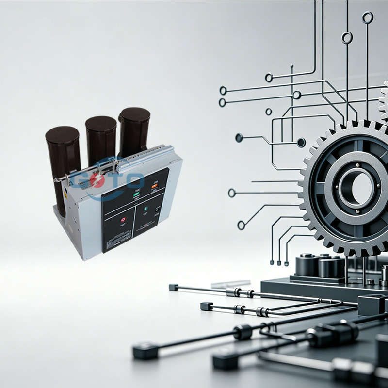
A vacuum circuit breaker (VCB) is an electrical switching device designed to interrupt current flow by extinguishing the arc within a sealed vacuum chamber. Unlike traditional oil or SF6 breakers, VCBs use a vacuum as the arc-quenching medium, significantly enhancing dielectric strength recovery and reducing contact erosion.
The core component is the vacuum interrupter, which contains the contact assembly where the current is interrupted. When the contacts separate, an arc forms, but it is rapidly extinguished due to the absence of gas molecules, which prevents sustained ionisation.
Protecting electrical circuits from overloads and short circuits
Enabling safe and fast switching operations under load
Enhancing overall power system reliability
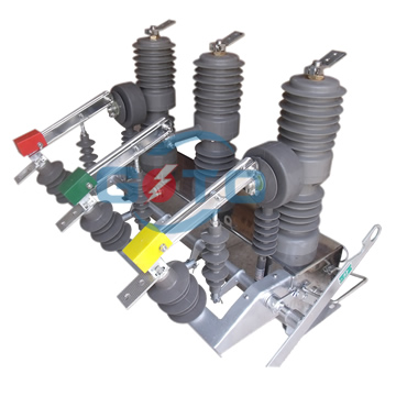
A vacuum circuit breaker consists of several essential components:
When a fault occurs, the operating mechanism triggers the contacts inside the vacuum interrupter to separate. As the contacts separate, an arc is formed due to the ionisation of metal vapours from the contact surfaces.
In a vacuum environment:
The absence of gas prevents the arc from elongating.
Ionized particles rapidly condense on the contact surfaces.
The vacuum pressure enables quick dielectric strength recovery, extinguishing the arc within 2–3 milliseconds.
A key factor in the breaking performance of VCBs is their ability to withstand Transient Recovery Voltage (TRV).
Definition: TRV is the rapid voltage rise that appears across the breaker contacts immediately after current interruption.
Significance: The steepness (rate of rise) and peak value of TRV can stress the insulation system and affect successful arc extinction.
VCB Advantage: Thanks to the very fast dielectric recovery of vacuum interrupters, VCBs can handle steep TRV waveforms typical in medium-voltage networks.
Application Note: In systems with long cables, capacitor banks, or highly inductive loads, TRV stress is more severe. Therefore, VCBs are type-tested according to IEC 62271-100 TRV requirements (T10, T30 duties) to ensure reliable performance under these demanding conditions.
This combination of fast arc extinction and superior TRV withstand capability makes VCBs highly reliable for medium-voltage applications.
When selecting a vacuum circuit breaker, consider the following technical parameters:
These parameters determine the suitability of the VCB for specific medium-voltage switchgear and high-voltage substation applications.
Ensuring the reliability and safety of a Vacuum Circuit Breaker (VCB) requires comprehensive testing procedures that comply with internationally recognized standards. The testing methods outlined below follow the guidelines specified in IEC 62271-100: High-Voltage Switchgear and Controlgear – Part 100: Alternating-Current Circuit-Breakers, which is the primary standard governing the design, testing, and operation of VCBs.
| Test items | Purpose | Method / Procedure | Standard Reference | Acceptance Criteria |
|---|---|---|---|---|
| Appearance Inspection | Detects physical defects or leakage | Visual check of casing, connectors, insulators, fasteners, interrupter seals | IEC 62271-100 (General) | No cracks, deformation, contamination, or leaks |
| Insulation Resistance Test | Evaluates insulation quality | Megohmmeter test between phase-to-ground and across open contacts | IEC 62271-100 | ≥ 1000 MΩ |
| AC Withstand Voltage Test | Assesses dielectric strength | Apply 1.5–2 × rated AC voltage phase-to-ground and across open contacts for 60s | IEC 62271-100 | No flashover or breakdown |
| Contact Resistance Test | Ensures low-loss conduction | Micro-ohmmeter across closed contacts | IEC 62271-100 | ≤ 30 μΩ; no overheating |
| Mechanical Properties Test | Validates mechanism durability | 50–100 operating cycles; check spring force, travel, latch reset, abnormal sound | IEC 62271-100 | Smooth operation, no fatigue or damage |
| Operating Mechanism Test | Verifies timing and synchronism | Timing analyzer measures opening/closing time, repeatability, and phase synchronism | IEC 62271-100 | Consistent timing; no delays or irregularities |
| DC Withstand Voltage Test | Assesses DC insulation capability | Apply rated DC voltage; monitor leakage current and PD behavior | IEC 62271-100 (Optional) | No abnormal leakage or discharge |
| Short-time & Peak Withstand Current | Confirms thermal & electrodynamic stability | Apply rated short-time current (e.g., 25kA/3s) and peak withstand current (e.g., 63kA) | IEC 62271-100 | No deformation, excessive heat, or failure |
| Breaking Capacity Test | Verifies rated short-circuit interruption | Perform O-0.3s-CO-3min-CO sequence for short-circuit, inductive, and capacitive loads | IEC 62271-100 | Successful interruption; no restrike or re-ignition |
| Partial Discharge Test | Detects insulation defects (voids, cracks) | Apply rated voltage; measure PD activity | IEC 60270 / IEC 62271-100 | ≤ 10–20 pC |
| Temperature Rise Test | Ensures safe operation under rated current | Run at rated load current; measure contact and conductor heating | IEC 62271-100 | ≤ 65K rise at contacts |
| TRV Withstand Test | Confirms ability to handle recovery voltage | Apply IEC TRV waveforms (T10, T30 duties) after short-circuit interruption | IEC 62271-100 | Withstand TRV without breakdown |
This is the initial step where visual inspection is carried out to detect any surface damage, deformation, contamination, or leakage. Key elements include:
This test uses a Megohmmeter to measure the insulation resistance between:
A reading above 1000 MΩ is typically expected. Low insulation values may indicate moisture ingress, material degradation, or contamination.
This test applies a high AC voltage (usually 1.5–2 times the rated value) across:
It is conducted for 60 seconds to evaluate the dielectric strength of insulation. No flashover or breakdown should occur during this duration.
A micro-ohmmeter is used to measure the resistance between closed contacts. Ideal values are below 30 micro-ohms.
Higher readings may suggest:
Low resistance ensures minimal heat generation and efficient conduction.
This test validates the mechanical robustness of the operating mechanism:
Using a timing analyzer, this test evaluates:
It helps detect issues with coils, lubrication, and control circuit delays.
Though not standard in all environments, this optional test assesses insulation behavior under DC voltage. It is especially useful in:
Leakage current levels and partial discharge behavior are monitored to ensure long-term reliability.
Purpose: Verifies the breaker can withstand the electrodynamic and thermal effects of fault currents.
Method: Apply rated short-time withstand current (e.g., 25kA for 3s) and peak withstand current (e.g., 63kA) without damage.
Criteria: No excessive heating, deformation, or failure of the interrupter.
Purpose: Confirms the VCB’s rated short-circuit breaking ability.
Scope:
Rated short-circuit breaking current
Capacitive and inductive current switching
Making capacity (first-pole-to-close duty)
Standard Reference: IEC 62271-100 operation sequences (e.g., O-0.3s-CO-3min-CO).
Purpose: Detects insulation defects such as voids or cracks.
Method: At rated phase-to-ground voltage, measure discharge activity.
Criteria: Partial discharge should remain below 10–20 pC per IEC requirements.
Significance: Ensures long-term reliability and prevents premature insulation failure.
VCBs offer several key advantages over other circuit breakers, like SF6 or oil-based types:
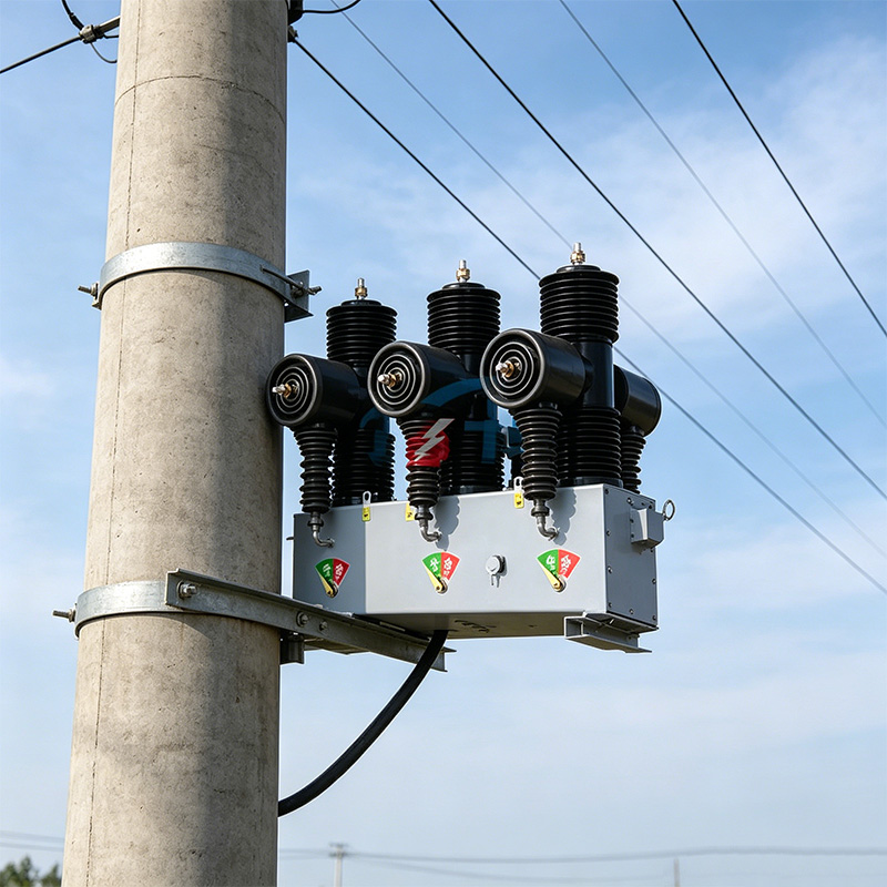
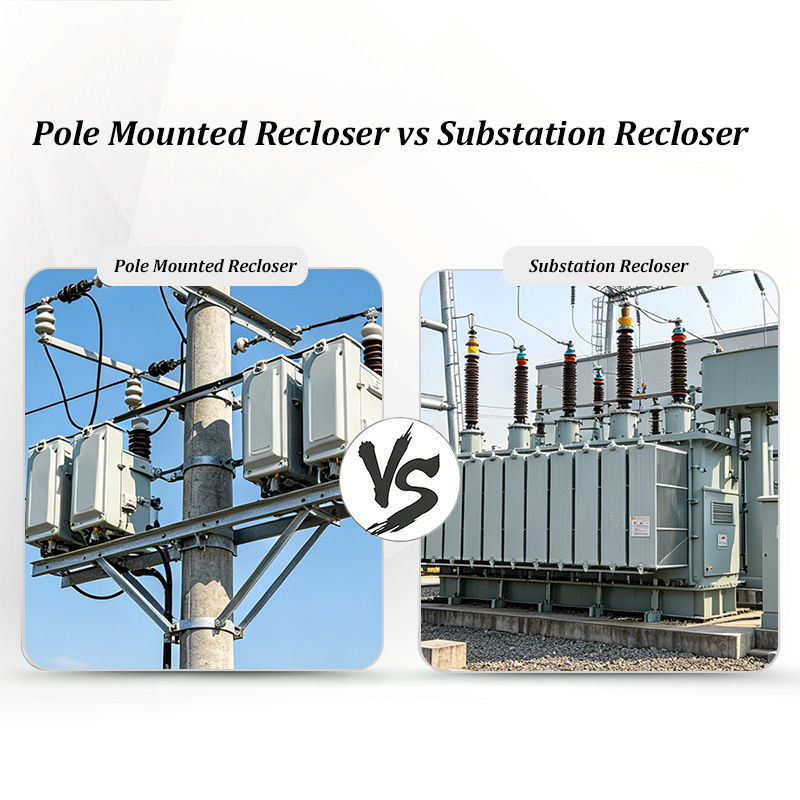
VCBs are suitable for a broad range of power system environments:
When choosing the right VCB, consider the following:
Compared to air circuit breakers (ACBs), VCBs offer significantly faster arc extinction, lower maintenance, and environmental advantages. For a detailed comparison between ACB and VCB technologies, see our dedicated article “ACB vs VCB – Key Differences Explained”
For a broader perspective on trusted manufacturers, check out our guide to the best vacuum circuit breaker suppliers, which highlights leading companies that meet these criteria worldwide.
Vacuum circuit breakers represent the future of medium-voltage protection. With high reliability, fast interruption, minimal maintenance, and environmentally friendly performance, VCBs are the ideal solution for modern power systems. Whether you’re an electrical engineer managing switchgear or a procurement manager sourcing high-performance circuit protection, VCBs offer unmatched long-term value.
By understanding their construction, operation, testing, and application, you can make informed decisions that enhance your power system’s safety and stability.
 Optimized by Seraphinite Accelerator